Motor Contactor Wiring Diagram

12 Volt 2 Way Switch Wiring Diagram, How to wire LED Lights & Use 2-Way switches | 12 Volt Planet, 7.8 MB, 05:41, 128,538, 12 Volt Planet TV, 2019-03-07T10:24:09.000000Z, 19, 12v Switch Wiring, www.chanish.org, 600 x 555, jpeg, 12vdc oznium volts dimmer chanish, 20, 12-volt-2-way-switch-wiring-diagram, Anime Arts
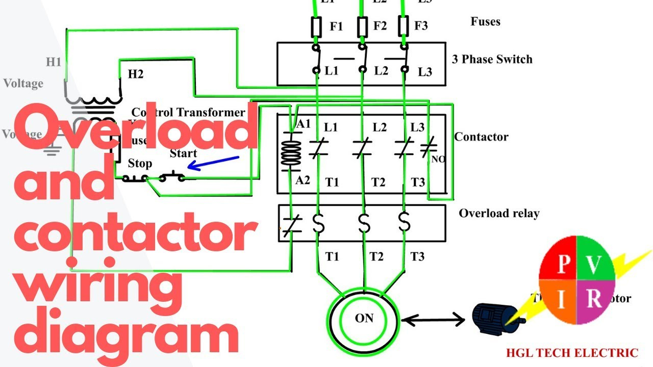
Wiring diagram direct on line motor starter gahzly can we use a 3 pole contactor for single phase controlled by dol with overload relay features if possible how do calculate the fault cur quora contactors electromechanical relays electronics textbook contactorotor starters schematic diy electric car forums electrical and protection schneider nigeria nema top loads. 3 phase forward reverse switch wiring diagram earth bondhon interlocking methods for reversing control basic circuits single 240v motor starter overload with on off doityourself com community forums magnetic an allen bradley 709 220v the hobby machinist 1 5cv 230v contactor adajusa and applied electricity electrical protection of motors types. Motor contactor wiring diagram. A wiring diagram is a simplified traditional pictorial representation of an electrical circuit.
Typically a contactor is activated by a remote switch or other controlling electrical device. 4 pole contactor with 4 n. o. Power poles 4 pole contactor with 2 n. o. /2 n. c. Power poles 3 pole reversing contactor set. 4 pole control relay with 4 n. o. Contacts 4 pole control relay with 3 n. o. / 1 n. c. Contacts 4 pole control relay with 2 n. o. / 2 n. c.
Single Phase Motor Contactor Wiring Diagram

Contactor Wiring Guide For 3 Phase Motor With Circuit Breaker, Overload Relay, NC NO Switches

Dol Starter Wiring Diagram 3 Phase Perfect Contactor Wiring Diagram Start Stop With Electrical
3 Phase Contactor Wiring Diagram Start Stop - Cadician's Blog

Wiring Manual PDF: 110 Single Phase Motor Wiring Diagrams

3 Phase Motor Wiring Diagram Contactor Relay | Fuse Box And Wiring Diagram

Furnas Motor Starter Wiring Diagram | Free Wiring Diagram

Single Phase Motor Wiring With Contactor Diagram - Electricalonline4u

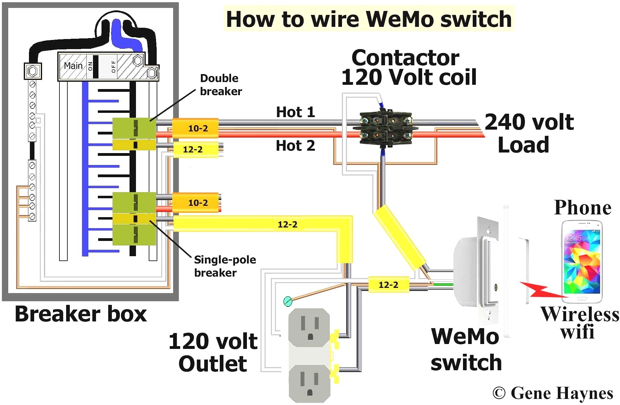
Wiring Diagram For 120v Coil Contactor - Complete Wiring Schemas

Get 3 Phase Contactor Wiring Diagram Start Stop Download
