120 220 Motor Wiring Diagram
Some manufacturers use different names for the terminals on their motors. 120 and 240 volt motor wiring do it yourself:

120 240 Volt Motor Wiring Diagram easywiring
15 simple wiring diagram for 220 volt.

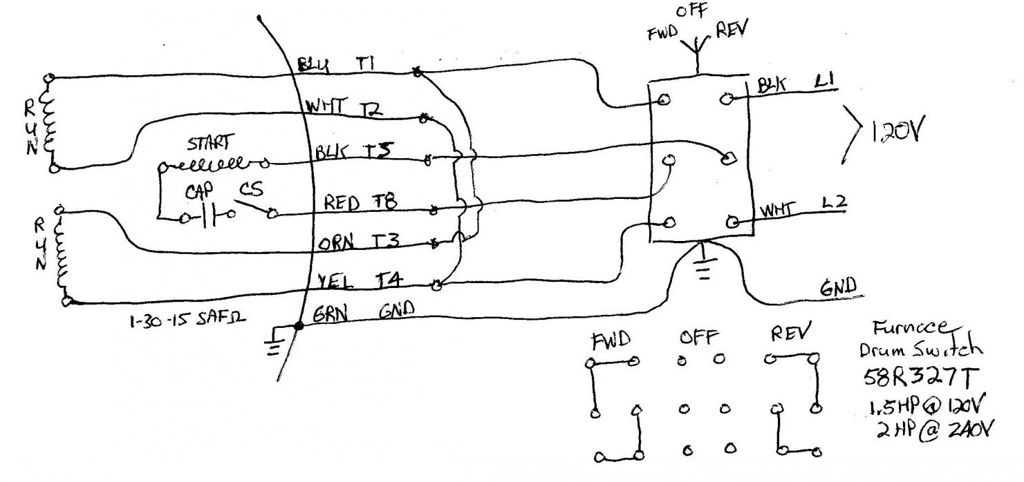
120 220 motor wiring diagram. I want to use the 220v fan assembly from a 1970s vintage electric furnace to provide ventilation in my workshop. 2 11 in which vector 1 is 120 degrees in advance of. But sometimes when you open up a motor, there's just six wires and no diagram!
Terminal markings and internal wiring diagrams single phase and polyphase motors meeting nema standards see fig. Honestly we have been realized that single phase forward reverse motor wiring diagram is being just about the most popular subject right now. Our best advice is not necessarily only look at the diagram, but understand how the constituents operate when in use.
To complete a single phase motor direction change, you will need to motors go in forward and reverse depending on their wiring and the resulting magnetic field. A universal electric motor is designed to operate on either alternating current or direct current (ac/dc). Dual voltage motors, how they work, and wiring them without the wire labels.
Inst maint & wiring_5.qxd 20/11/2015 11:37 am page 7 A schematic diagram of a forward reverse control for a single phase split phase motor. The function is the exact same.
It is provided with a field winding on the stator which is connected in series with a commutating winding on the rotor. 220 electric motor wiring diagram 220v century single phase motors. 220v wiring ask the electrician:
A photo of the wiring diagram inside the old furnace is at the end. The advantages of a 240 volt motor. 5744b52 electric motor wiring diagram 110 to 220 library 120 240 volt vac 1971 triumph spitfire for schematics terry love plumbing advice remodel diy professional forum tk 6191 single phase on free kv 6567 schematic dlpf.
220v motor wiring diagram source: Refer to the motor manufacturer s data on the motor for wiring diagrams on standard frame ex e ex d etc. As i read it, there are six wires to the motor.
Subsequent diagrams is pretty simple, but using it in the scope of how the device operates is a new different matter. Wiring a 120/240 volt motor for 240 volts is as follows: Inst maint & wiring.qxd 5/03/2008 10:02 am page 6
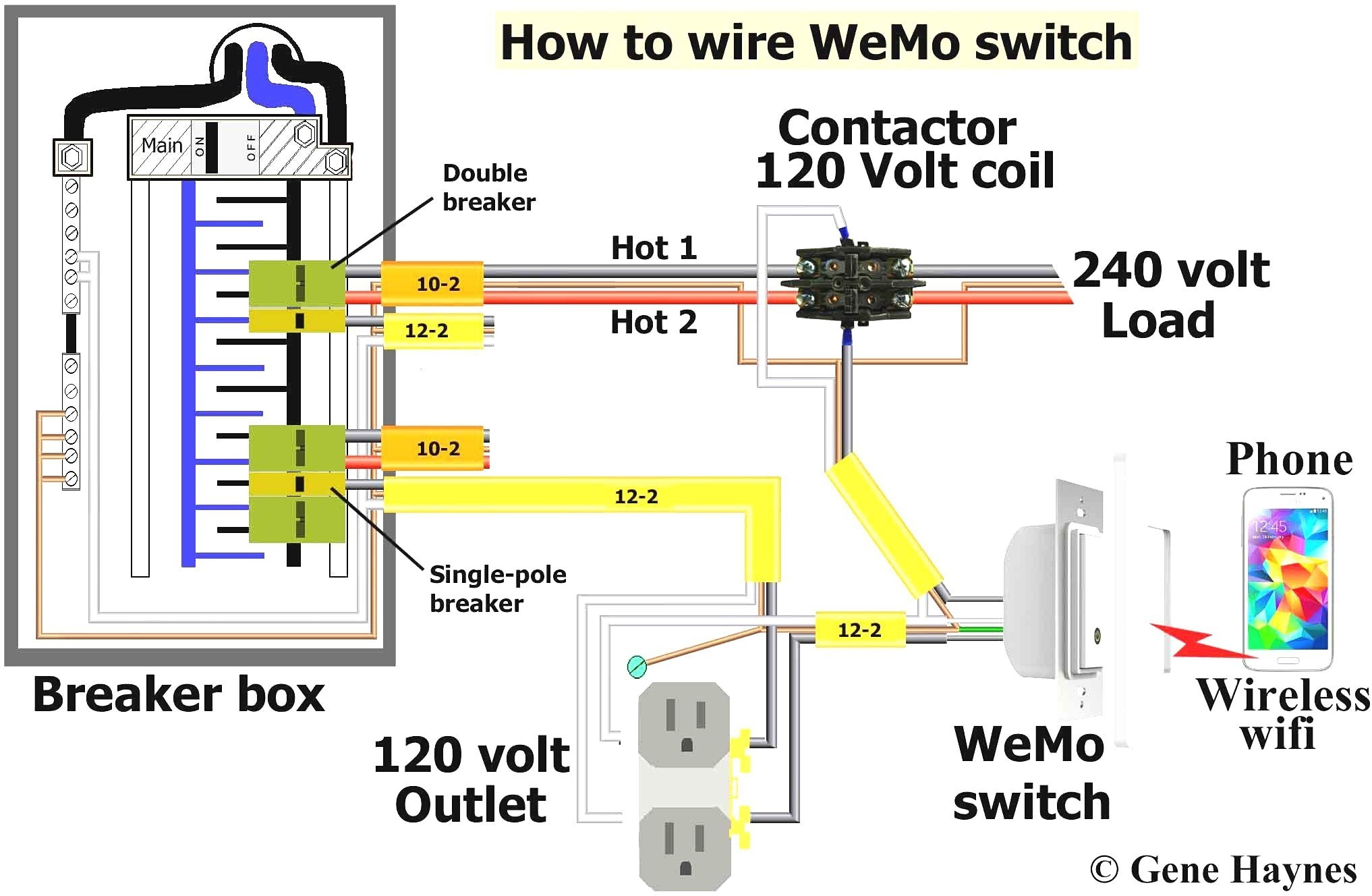
Here are some considerations when trying to provide a source for 110 volt or 120 volt power: 120 volt 3 speed fan motor wiring diagram. For where i moved it to.
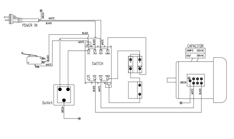
120 volt and 220 volt electrical circuit wiring. 220v motor wiring diagram source: 120v ac capacitor motor reversing switch wiring diagram.
Otherwise, the structure won’t work as it ought to be. Each part ought to be set and connected with other parts in particular way. Each part should be set and linked to other parts in particular way.
Ask that they not flip any breakers or switches until you are finished. 220 volt circuit diagram unique 4 wire 220 volt wiring diagram. Therefore 220 230 and 240 volts are all interchangeable and wired the same.
White and brown wires connect to a large capacitor like device. With larger motors there may be a larger junction box with lead wires that are identified with numbers or letters which will be identified by the wiring diagram of the specific motor. It has a 3 speed fan motor.
For specific leeson motor connections go to their website and input the leeson catalog # in the review box, you will find connection data, dimensions, name plate data, etc. Electric motor wire marking & connections. Honestly, we also have been noticed that 3 wire 220v wiring diagram is being one of the most popular subject at this moment.
It is a series wound motor. Reconfiguring between 240 and 120 volts is done the same way but the starter winding stays connected to one of the windings. See photos of wiring diagram and motor nameplate.
The original motor was a three phase 480 volt reversible motor which was operated by the cutler hammer 9441h37b o series controller. These diagrams are current at the time of publication, check the wiring diagram supplied with the motor. Airflow airflow airflow airflow * * these diagrams are current at the time of publication, check the wiring diagram supplied with the motor.
This happened to be the case for the 1.5 hp motor on my old table saw. The best way to change the voltage on a motor is to follow the wiring diagram on the label. To reverse rotation on a single phase capacitor start.
How to decipher the wiring schematic of a 110/220v single phase motor? Understanding 120/240v wiring color code galco: Refer to the motor manufacturer’s data on the motor for wiring diagrams on standard frame ex e, ex d etc.
20 years ago i wired it to 240 volts, but i wanted to switch it back to 120 volts.
Wiring for Laguna Saw 1 phase or 2?
Bought used bridge port need help to plug it in!

120 240 Volt Motor Wiring Diagram schematic and wiring diagram


Wiring Diagram For 220 Volt Single Phase Motor, http//bookingritzcarlton.info/wiringdiagram
120 Electrical Wire Colors Brilliant 220 Volt Wiring Diagram Natebird Me Striking Colors


120v Plug Wiring Diagram
120 Volt Breaker Wiring schematic and wiring diagram


120 Volt Electric Motor Wiring Diagram Single Phase schematic and wiring diagram
220 Motor Wiring Diagram Wiring Diagrams

Wiring a single phase motor to drum switch Page 2

120 Volt Electric Motor Wiring Diagram Single Phase schematic and wiring diagram

Wiring Diagram Of Single Phase Motor Home Wiring Diagram
How To Wire A, Light Perfect 240 Volt Light Wiring Diagram Floralfrocks, 4 Wire, For Photos

How to know if equipment needs 240 volts or 120 volts to work Quora

120 Husky Air Compressor Wiring Diagram
Wiring help needed for a 1phase 220v reversing puzzle South Bend Mill


Wiring Diagram For 220 Volt Single Phase Motor bookingritzcarlton.info Diagram, Electric
Reversing a lathe

Wiring help needed for a 1phase 220v reversing puzzle South Bend Mill