Tohatsu Ignition Switch Wiring Diagram
Ignition (switch) to 12 volt positive : Here are a number of highest rated yamaha outboard motor wiring diagram pictures on internet.
Tohatsu Outboard Motor Wiring Diagram Wiring Diagram
It is recommended that insulated wire terminals, preferably ring type, be used on all connections to the

Tohatsu ignition switch wiring diagram. As a service to our customers, copies of our owner's manuals are available for download at no charge: If you have trouble viewing the. The manuals are in adobe's pdf format.
2cyl engines 40c, 50c & 50a, 70a, ns25c, ns30a,. We identified it from reliable source. Tohatsu m120a2 140a2 parts list 2003 tohatsu m40c parts list 2004 tohatsu outboards tohatsu 5hp, 8hp, 9.
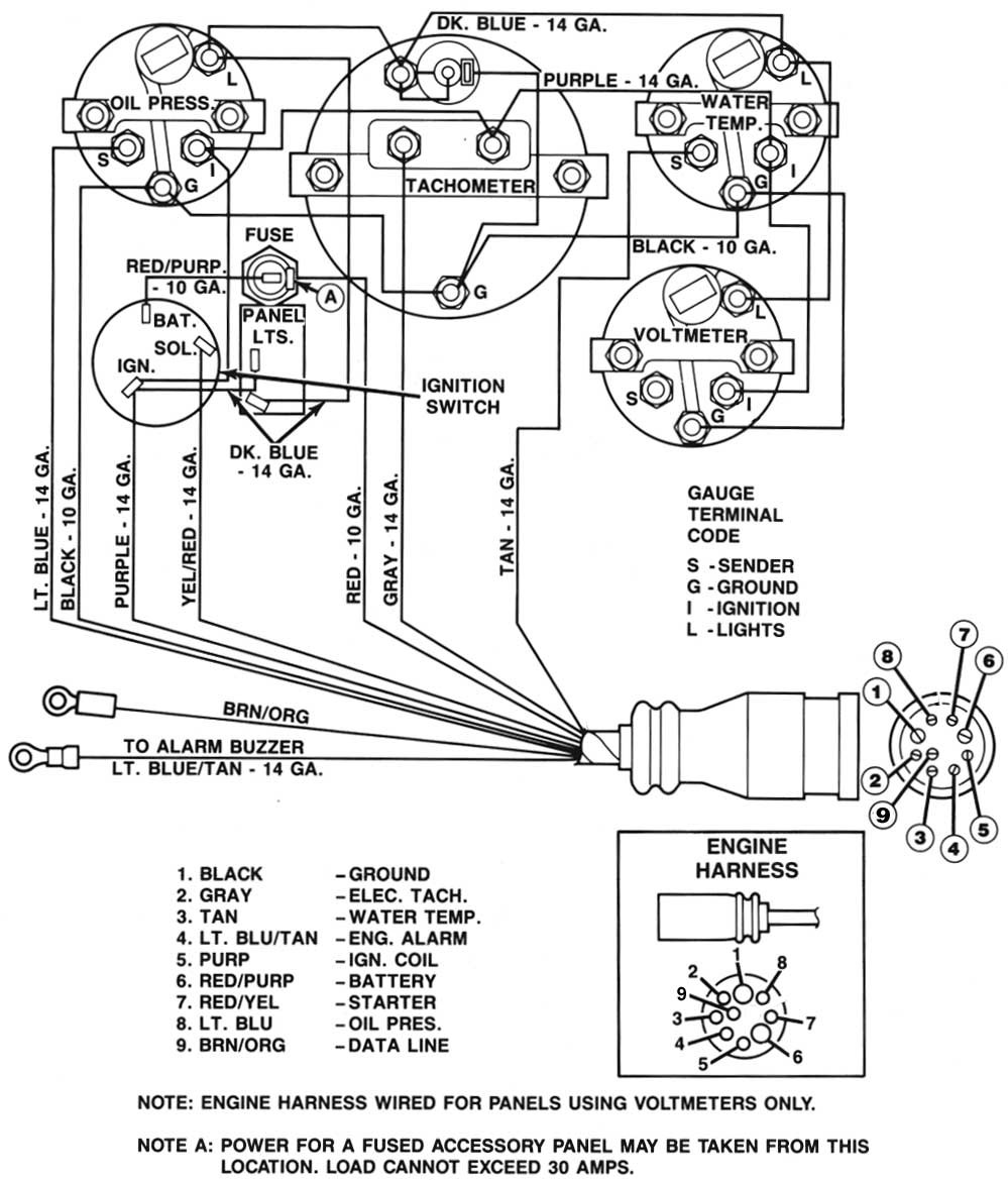
Ignition switch brass terminals on switch wiring diagram for 4 position universal ignition switch product code p00940 Red / purple stripe : (see diagram on the next page for connections) standard case 5.
Connect the opposite end to a 12vdc circuit that is activated by the ignition switch. Tan / /blue stripe : Look at that diagram on page 47, there is the flow chart just like the one on a merc service manual for the key switch.
If not, the structure won’t. In order to download/view the manuals you must have the adobe acrobat reader installed on your computer. Temperature switch to warning horn and/or temperature sender to temperature gauge :
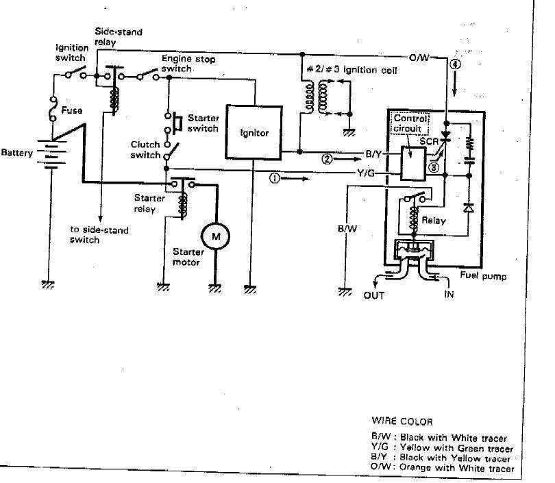
Connect a wire to the tach stud marked “bat” (battery) and secure with a nut and lockwasher. Radio, lights, cigar sockets etc. To ignition system to starter motor solenoid to accessories e.g.
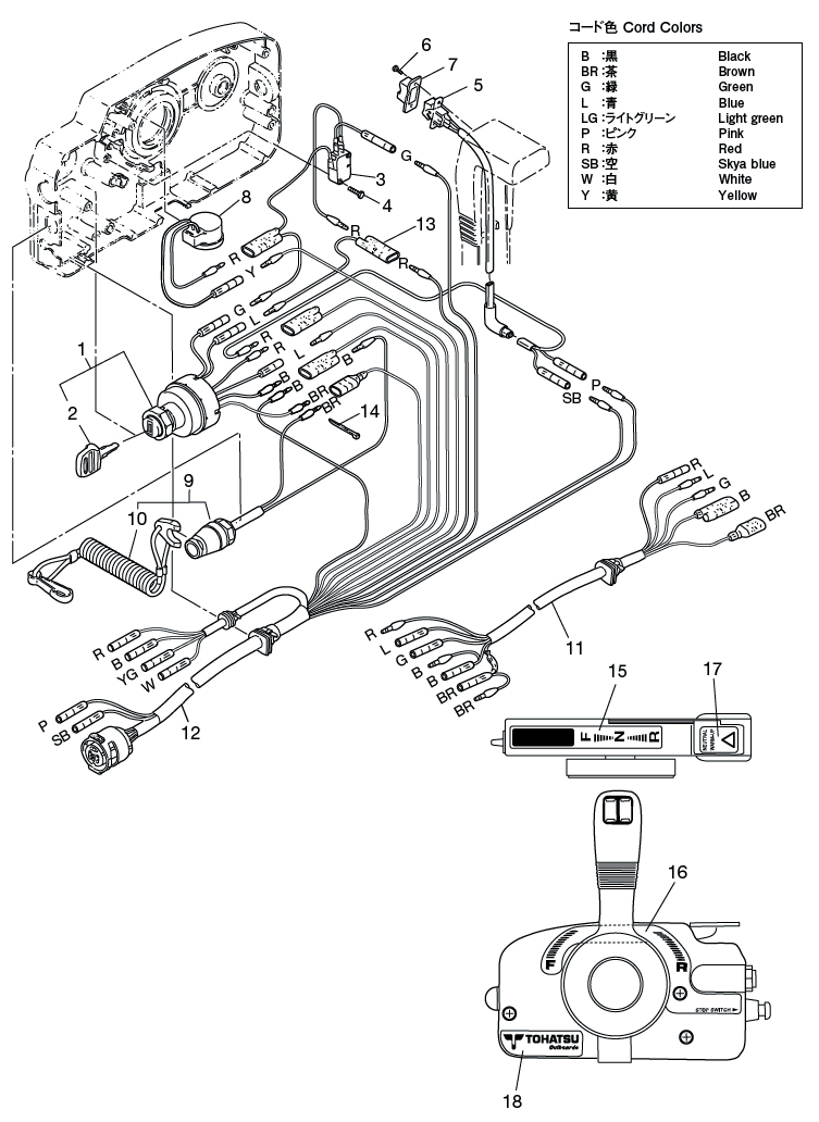
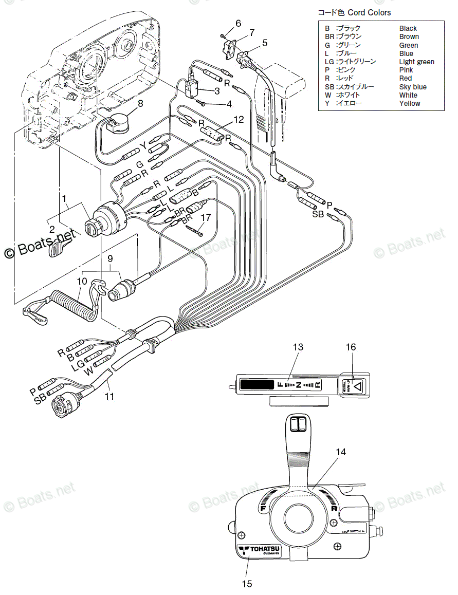
First color is the primary color of the wire. All that tohatsu shows are the two reds for on, green is start, blue is choke, brown and black are stop. Novelbee side mount remote control box with 10 pins wire harness and cable 16ft for yamaha outboard motors steering system right hand 703 48205 online in vietnam b07z8w7n6x
Emergency stop switch the emergency stop switch will stall the outboard motor when the stop switch lanyard is pulled off. Up to 20% cash back marine mechanic: A wiring diagram is a simplified traditional photographic depiction of an electric circuit.
We endure this nice of yamaha outboard motor wiring diagram graphic could possibly be the most trending subject afterward we ration it in google plus or facebook. Omc marine ignition switch wiring diagram daily update wiring mercury outboard wiring harness diagram wiring diagram mercury 6 hp 15 shaft outboard motor built in fuel tank 6mh Power red red red red red red/purple white red.
Circuit is normally closed (complete) with lanyard clip in place on switch. Protected (fused) wire from battery and/or protected (12 volt +) to trim panel control : If there is a second color listed, it is the color of the trace.
This stop switch lanyard has to be attached to the operator of the outboard. Alternate color temperature switch to warning horn : The stripe color on the tan wire indicates the temperature at which the sensory trips.
As always, for tohatsu ob products, year of manufacture is irrelevant. Ignition instrument power ignition switch to coil and electrical instruments. ( click here to download the free acrobat reader program.) note:
Tohatsu 5 bs owner s handbook manual pdf manualslib. Used on switch #'s m & m find great deals on ebay for tohatsu ignition. Assuming you have a remote motor, but no controls.
Rc boat water cooling parts; Made of stamped brass and molded nylon. How to wire the kill switch.
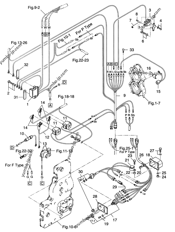
Its submitted by presidency in the best field. 8e8eb tohatsu 30hp wiring diagram wiring resources tohatsu outboard control wiring diagram top electrical wiring. Tohatsu m50d2 50 hp outboard motor electric parts for mfs15c mfs25b mfs9 8a3 9 8 m70c 70 diagram remote control mfs30b ecu switch box f type md50b2 9c ns8b mfs8a3 seloc marine nissan outboards wiring manual 1956 1989 8hp starter battery cable 5 bs owner s handbook fuel system 6a3z mfs.
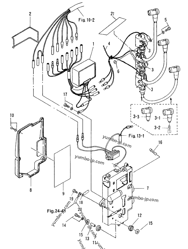
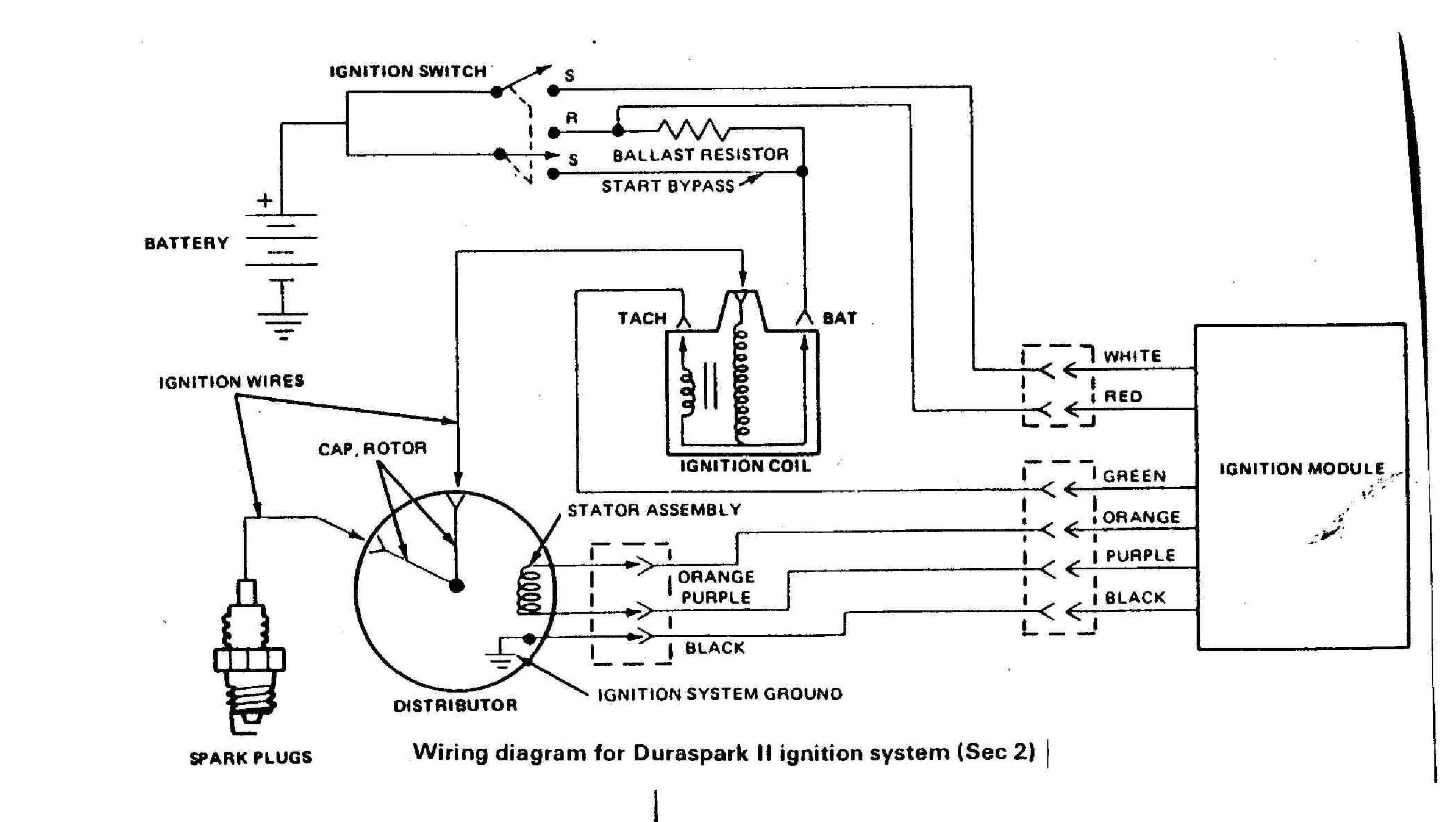
Tohatsu nissan genuine oem outboard motor part number 3h6060500m ignition coil. Note that for a one cylinder engine there is a direct electrical path from the plug cap through the hv wire, and coil to the engine. Refer to the electrical diagram in figure 1.
Charles, marine mechanic replied 6 years ago. Tohatsu color codes are standard from year to year. Ignition system battery ignition spark plug ngk ikr6g8 alternator a21 trim.
Add anything you want via xstore header builder coffee bean decaf drinks (c) the white/black wire is the cold engine temp indicator and shorts to gnd. Possibly a rebadged mfs30b, since it's more than 1 or 2 years old.
Each part should be placed and linked to different parts in specific manner.

Yamaha Key Switch Wiring Diagram Sample

50 hp tohatsu 2 strokes when turning ignition key no power trim and motor also 12 volts ok on

[NO_4349] Tohatsu 90 Hp Outboard Wiring Diagram Download Diagram

M40c Tohatsu Wiring Diagram

Tohatsu Ignition Switch Wiring Diagram ekoputerasampoerna
Tohatsu Lcd Multimeter Wiring Diagram

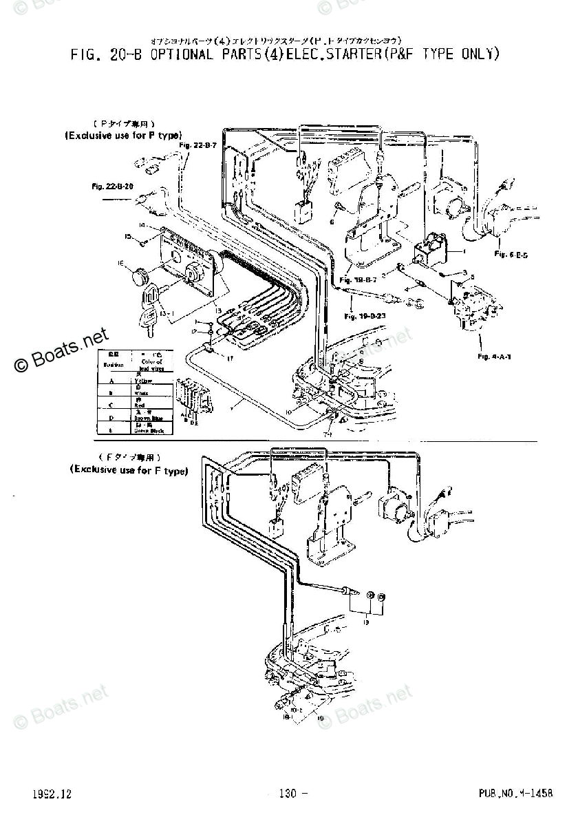
Tohatsu 1996 M40C 2 Stroke Tohatsu OEM Parts Diagram for Electric Starter (P & F Types
Wiring Diagram PDF 100 Johnson Wiring Harness Diagram

Where To Hook Tach To On Ignition Key Switch On An Omc Evinrude For Wiring Diagram For Boat
Tohatsu Outboard Motor Wiring Diagram Wiring Diagram

[NO_4349] Tohatsu 90 Hp Outboard Wiring Diagram Download Diagram
Ignition Wiring Forums
Tohatsu Outboard Control Wiring Diagram Complete Wiring Schemas
[DIAGRAM] 40 Hp Tohatsu Wiring Diagram FULL Version HD Quality Wiring Diagram SCHEMATICFILEH
[NO_4349] Tohatsu 90 Hp Outboard Wiring Diagram Download Diagram
[DIAGRAM in Pictures Database] 2005 Suzuki Outboard Wiring Diagram Schematic Just Download or
[DIAGRAM] 40 Hp Tohatsu Wiring Diagram FULL Version HD Quality Wiring Diagram SCHEMATICFILEH

Tohatsu Outboard Control Wiring Diagram Complete Wiring Schemas

[DIAGRAM] Johnson Outboard Wiring Diagrams 50 Hp Pulse Pack FULL Version HD Quality Pulse Pack